Detail Drawings Explained
Learn how to read architectural detail drawings: what they show, how detail callouts point to them, and why they matter for construction accuracy.
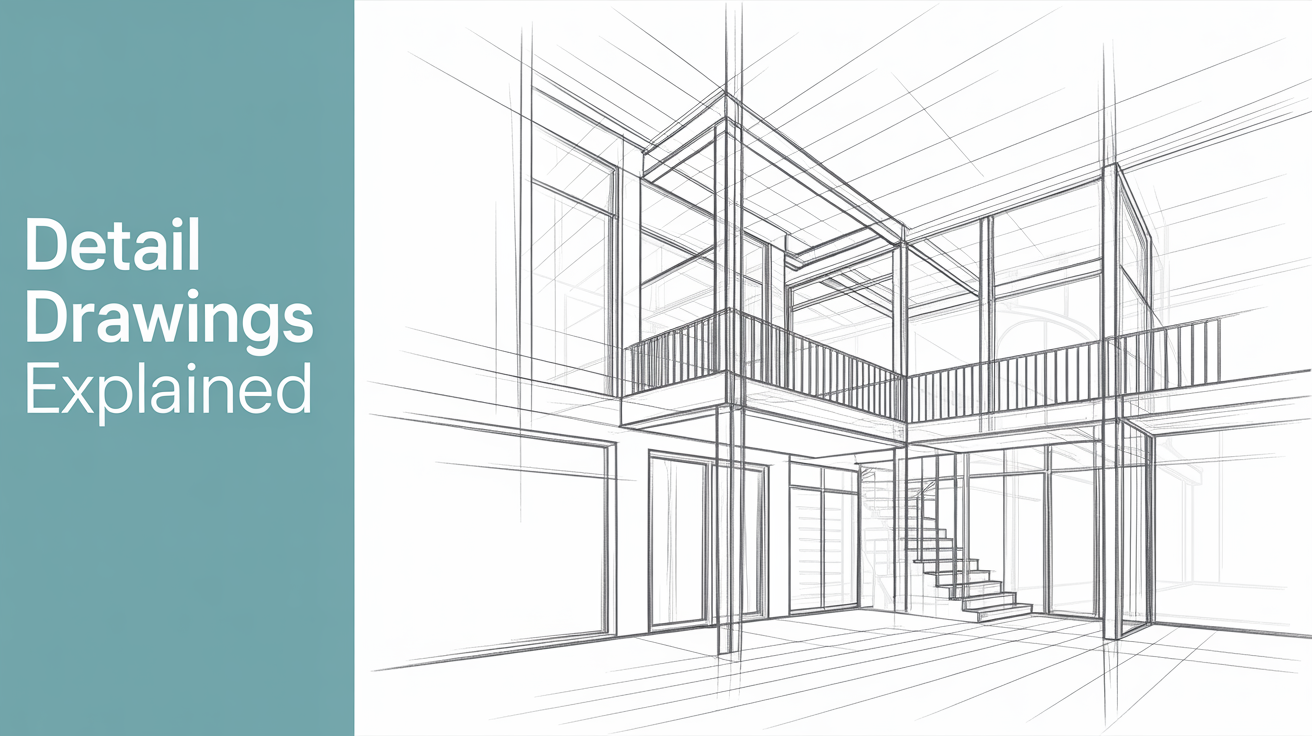
A detail drawing is a close-up view of one specific part of a building, drawn at a much larger scale than the rest of the set so you can see exactly how something goes together. If a floor plan tells you where a wall sits and an elevation shows how tall it is, a detail drawing tells you what is inside it: the layers, the fasteners, the flashing, the exact dimensions a framer or mason needs to build it correctly. This guide walks through what architectural detail drawings show, how to find and read the callouts that point to them, and how to use them with no drafting background.
What a Detail Drawing Actually Shows
Think of a detail drawing as a zoomed-in slice through a piece of construction. Most of a drawing set is drawn "small," at a scale like 1/4 inch equals one foot, because it needs to show a whole building on one sheet. At that scale a wall is just a thin line. You cannot see the insulation, the vapor barrier, the trim profile, or how the roof meets the wall.
A detail drawing solves that by cutting a small section of actual building, often just a few inches or feet, and blowing it up to a much larger scale, commonly 1 inch equals 1 foot or even 3 inches equals 1 foot. At that size there is room to label every layer and material by name, note exact dimensions, and show how pieces overlap, fasten, or seal against each other.
Construction details usually fall into two families. Section details are vertical slices, showing how something is built from bottom to top, like a foundation-to-floor connection or a window sill. Plan details are cut horizontally, looking down, and are common for stair layouts or how a wall meets a column. Both work the same way: cut through the object, then draw exactly what that cut exposes.
How Detail Drawings Fit Into the Larger Set
Detail drawings never stand alone. They exist to answer a question that a smaller-scale drawing raises but cannot fully answer, so they are always tied back to the rest of the set through callouts and cross-references. If you are new to the full set of sheets a project includes, this overview of what's in a set of construction drawings is a useful place to start before you dig into details specifically.
In practice, the flow looks like this. A floor plan or building section shows the general layout of a wall, roof, or floor assembly. Somewhere on that drawing, a small symbol marks the exact spot the detail applies to and points to a sheet number where the enlarged detail lives. On that sheet, the drawing carries labels, dimensions, and material notes that spell out exactly how to build that one piece.
This layered approach keeps the main plans readable. Nobody wants a floor plan cluttered with insulation thickness and fastener spacing for every wall. Instead, the plan stays clean at building scale, and the specifics live in details you pull up only when you need them.
Reading a Detail Callout Step by Step
The callout is the small graphic symbol on a plan, elevation, or section that tells you a detail exists and where to find it. Once you know the pattern, reading detail callouts becomes second nature.
Most callouts use a circle or hexagon split into two halves by a horizontal line. The top half holds a number or letter, which identifies the specific detail. The bottom half holds a sheet number, which tells you which drawing to turn to. So a callout reading "4" over "A-501" means: this is detail 4, and you will find it drawn out on sheet A-501.
Attached to that circle is usually a short line with an arrowhead pointing at the exact location the detail describes. That arrow tells you which corner, edge, or connection the enlarged drawing covers, which matters because a single wall might have several details called out along its length: one at the base, one at a window, one at the roofline.
Here is a simple way to work through any callout you find on a plan:
- Find the symbol on the plan, section, or elevation, and note what it points at.
- Read the top number or letter, the detail's identifier.
- Read the bottom value, the sheet where that detail is drawn.
- Turn to that sheet and locate the matching detail number.
- Read the detail's title, scale, and labels before interpreting the drawing itself.
- Check the detail again against the plan location so you know which real-world spot it describes.
Once you land on the detail sheet, look at the title block above the drawing first. It usually repeats the detail number, states the scale, and gives it a short name like "Typical Eave Detail" or "Foundation Wall Section." That title alone often tells you most of what you need before you even study the lines.
Common Types of Detail Drawings
New readers often assume "detail" means one kind of drawing, but the category covers a wide range of conditions. Here are the details you will run into most often on a residential or light commercial set.
| Detail type | What it typically shows | Where you will see the callout |
|---|---|---|
| Foundation detail | How the footing, foundation wall, and framing above connect | Building sections, foundation plan |
| Wall section detail | The full layer stack of an exterior wall, from siding to interior finish | Building sections |
| Roof eave or ridge detail | How the roof edge or peak is framed, vented, and flashed | Roof plan, building sections |
| Window or door head/sill detail | Framing and flashing around an opening | Elevations, wall sections |
| Stair detail | Rise, run, railing height, and connections | Floor plans, sections |
| Waterproofing or flashing detail | How water is directed away from a joint or penetration | Wall sections, roof details |
Not every project uses every one of these, and some add details for an unusual condition, like a custom fireplace surround. The point of a detail stays the same: it answers a question a smaller drawing cannot answer on its own.
If you want to see how a detail relates to the bigger geometry of the building it belongs to, comparing it against an elevation drawing of the same wall can make the connection clearer, since the elevation shows where that detail sits within the whole facade.
A Few Traps Beginners Fall Into
A handful of habits will save you time when you start reading details on your own.
Always check the scale noted on the detail itself. Because details are drawn much larger than the rest of the set, a dimension that looks small on the page can represent a large real-world measurement, or the opposite. Never assume a detail shares the scale of the plan it was called out from.
Remember that details show a slice, not the whole picture. A section detail through a wall will not show what that wall looks like from the outside, and a plan detail looking down at a corner will not show its height. You often need to view a detail alongside a plan, an elevation, or another section to build the full picture, which is part of why cross-referencing between sheets matters.
Do not skip the material labels and notes. The lines in a detail show shape and position, but the small text naming each layer, fastener, and material is often the most important part of the drawing. A framer or contractor reading the same detail relies on those notes as much as the lines themselves.
Finally, construction details explain typical conditions for a specific project, place, and code. Materials, fastening patterns, and clearances in one set of details are not automatically correct for your project. Always confirm details against your local building department's requirements, and have a licensed architect or engineer review any real construction plans before work begins.
Frequently Asked Questions
What is a detail drawing in construction?
A detail drawing is an enlarged, close-up drawing of one specific part of a building, such as a wall section, a foundation connection, or a window opening. It is drawn at a much larger scale than the main plans so it can show exact dimensions, materials, and how components fit and fasten together.
How do I find the detail that matches a callout?
Look at the two-part symbol on the plan, section, or elevation. The number or letter in the top half identifies the detail, and the value in the bottom half tells you which sheet it is drawn on. Turn to that sheet and match the number to find the enlarged drawing.
Why are some details drawn as sections and others as plans?
The choice depends on what best shows the condition being described. A vertical slice, or section detail, is used when the important information runs top to bottom, like a wall assembly. A horizontal slice, or plan detail, is used when the information is about layout as seen from above, like a stair or a corner condition.
Do I need to understand every detail on a set of plans?
Not necessarily. As a beginner, focus on details relevant to what you are evaluating, such as a renovation area or a condition you have questions about. For anything you plan to build from, or if a detail touches safety, structure, or code compliance, have a licensed architect or engineer walk you through it rather than relying on your own reading.
Can I use a detail from one project on a different building?
You generally should not copy a detail as-is between projects. Details are drawn for a specific building, site, climate, and local code, so a detail that works on one project may not meet requirements or perform correctly on another. Treat details as examples to learn from, and confirm specifics with your local building department and a licensed professional for your own project.