How to Draw a Floor Plan in CAD
A beginner's walkthrough for how to draw a floor plan in CAD, from setting up scale and units to placing walls, doors, and dimensions.
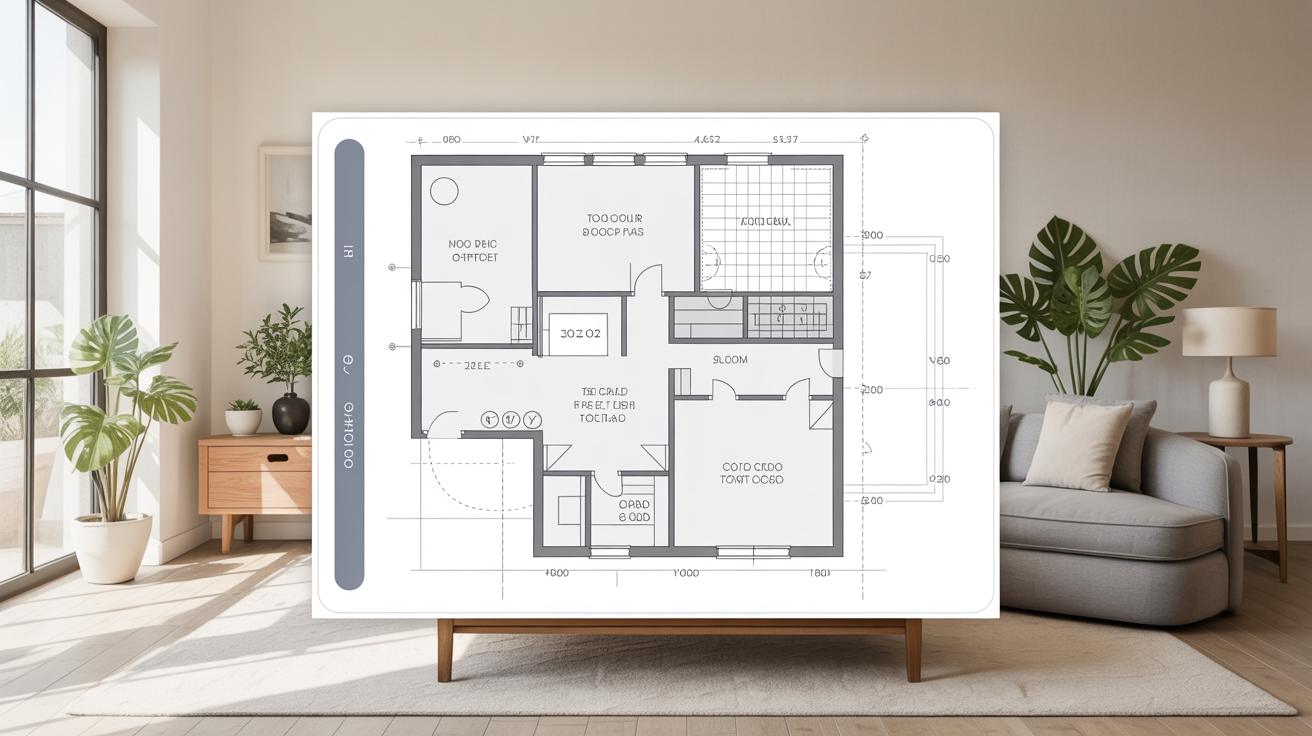
If you want to know how to draw a floor plan in CAD, the short version is this: set your drawing to real-world scale, lay out walls as accurate lines or wall objects, add doors and windows as blocks, then dimension and label everything so anyone can read it back correctly. The tricky part isn't clicking the right tool. It's understanding what each piece of the drawing represents and why the order you build it in matters. This guide walks through that process step by step, using terms that apply across most CAD programs rather than the menu names of any one brand.
If you're brand new to plan reading in general, it helps to start with architectural drafting for beginners before you dive into drawing your own. Knowing how a professional plan is put together makes it much easier to build one yourself.
Setting Up Your Drawing Before You Draw a Single Wall
Every CAD floor plan starts with two decisions that shape everything else: units and scale. Skip this step and your walls will look right on screen but measure wrong in real life.
Draw at full scale, then scale the output. Most beginners assume they need to shrink their drawing to fit a sheet of paper, the way you would sketch by hand. In CAD, you do the opposite. You draw everything at its true, full-size measurement (a 10-foot wall is drawn as 10 feet), and the software scales the whole drawing down only when it's time to print. This one habit prevents almost every measurement error a beginner runs into.
Pick your units and stick with them. Decide whether you're working in feet and inches or millimeters and set that at the start of the project. Switching partway through a drawing is where fractional errors creep in.
Set up layers before you place a single line. Layers let you separate walls, doors, windows, dimensions, and text so you can turn any category on or off, or change its line weight, without touching the others. A simple starting layer set might look like this:
| Layer name | What goes on it |
|---|---|
| Walls | Exterior and interior wall lines |
| Doors-Windows | Door swings, window symbols |
| Dimensions | All measurement lines and text |
| Fixtures | Plumbing, appliances, built-ins |
| Text-Labels | Room names, notes, titles |
| Furniture | Optional layout furniture, easy to hide for a cleaner print |
If line weights and layers still feel like a foreign language, drawing scales and line weights explained breaks down why heavier lines mean something different from lighter ones on a finished plan.
Drawing the Walls
Walls are the skeleton of a floor plan, so get them right before you add anything else.
Most CAD programs give you two ways to build walls: draw them as a pair of parallel lines at your chosen thickness, or use a dedicated wall tool that draws a single centerline and applies thickness automatically. The wall tool is faster and keeps your thickness consistent, which matters more than it sounds like it would. A wall drawn a half-inch off in a dozen places adds up to a floor plan that doesn't close correctly.
A practical sequence that keeps beginners from getting lost:
- Draw the exterior wall outline first, working around the full footprint of the building before you touch a single interior wall.
- Add interior walls next, snapping their endpoints to the exterior walls so every corner is clean and connected.
- Leave door and window openings as gaps for now. Placing the wall segments around them, rather than drawing solid walls and cutting holes later, avoids stray line fragments.
- Use your snap and grid settings constantly. Free-clicking wall endpoints without snapping is the single biggest source of walls that look aligned but are actually off by a fraction of an inch.
Work at a comfortable zoom level and check your wall thickness against a real-world reference. Standard interior walls typically run from about 4 to 6 inches finished, and exterior walls run thicker to account for insulation and siding. These numbers vary by construction type and region, so treat them as a starting point rather than a rule.
Adding Doors, Windows, and Dimensions
Once the walls are up, the drawing starts to read like an actual floor plan.
Doors and windows come from your library, not from scratch. Nearly every CAD program ships with a library of door and window blocks at standard sizes. Drop them into the wall openings you left earlier, and the software will usually show the door swing automatically, the quarter-circle arc that tells you which way the door opens and how much floor space it needs to clear.
Dimension every wall segment, not just the overall footprint. A floor plan with only outer dimensions is nearly useless to a builder. Add a full string of dimensions along each exterior wall showing every opening and wall segment, plus interior dimensions for room sizes and hallway widths. Keep dimension lines a consistent distance from the walls and from each other so the drawing doesn't turn into a tangle.
Use the CAD program's own measuring tools to double-check yourself. Before you trust a dimension, hover or click to read the actual length of the line the software drew. It's easy to nudge a wall a fraction of an inch by accident, and the software will happily dimension the mistake right along with everything else.
This is also the stage where a lot of beginners realize their first attempt at software choice matters. If you're still deciding what to draw in, best free floor plan software for beginners compares a few solid starting options before you commit hours to one program.
Labeling Rooms and Finishing the Plan
A technically accurate floor plan still needs labels before it communicates anything to another person.
Add a room name and square footage to every enclosed space. Most CAD programs calculate area automatically once a room is bounded by closed walls, so let the software do the math rather than adding it up by hand. Add a title block with the project name, date, drawing scale, and your name or company, even if this is just a practice drawing. It builds the habit early, and it's the first thing a reviewer looks for on a real set.
A few finishing touches that separate a rough sketch from a plan someone else can actually use:
- North arrow, so the orientation of the building is unambiguous.
- A drawing scale note, stated plainly (for example, a quarter inch equals one foot) in addition to whatever scale bar your software adds.
- Consistent text height across all labels, usually one size for room names and a smaller size for dimension text.
- A legend for any symbols that aren't self-explanatory, especially electrical or plumbing symbols if you've included them.
Checking Your Plan Before You Rely On It
Before you print, save, or share a CAD floor plan, walk it through a short review.
Zoom in on every corner where walls meet and confirm they actually connect, with no gaps and no overlapping lines. Check that every door swing has room to open without hitting a fixture or another door. Add up your interior dimensions along each wall and confirm they match the exterior dimension for that same wall. Confirm your scale note matches what you actually set in the drawing, since a mislabeled scale will throw off anyone who tries to measure directly off a printed sheet.
Remember that a CAD drawing you make while learning is a study tool, not a construction document. Drawing conventions, required symbols, and permit submission rules vary from one building department to the next, so before any real project moves forward, confirm the specifics with your local building department and have a licensed architect or engineer review the actual plans.
Frequently Asked Questions
Do I need to know AutoCAD specifically to draw a floor plan in CAD?
No. The steps in this guide apply to most CAD and floor-plan software, since they all handle scale, walls, dimensions, and labeling in a similar order, even though the exact menus and tool names differ. If you want to draw a floor plan in AutoCAD specifically, the workflow is the same: set units and scale first, then build walls, then add openings and dimensions.
What scale should I use for a residential floor plan?
A quarter inch equals one foot is the most common scale for residential floor plans in the United States, since it fits a typical house on a standard sheet while staying readable. Larger or more detailed drawings sometimes use a larger scale. Whatever you pick, draw at full size in the software and only apply the scale when you print or export.
Why do my walls look connected on screen but the room area calculates wrong?
This almost always comes down to snapping. If a wall endpoint looks like it touches another wall but isn't snapped exactly to it, the software may not recognize the space as a fully closed room, or it may calculate area based on a tiny gap you can't see at normal zoom. Zoom in tight on every corner and re-snap any endpoint that isn't locked to the wall it's supposed to meet.
Is a beginner CAD floor plan good enough to submit for a building permit?
Not on its own. A practice or planning drawing helps you communicate your ideas and catch obvious layout problems, but permit sets have specific requirements for symbols, notes, and structural information that vary by jurisdiction. Treat your CAD floor plan as a starting point, then work with your local building department and a licensed architect or engineer to turn it into a document that meets your area's actual submission requirements.