How to Read a Floor Plan
Learn how to read a floor plan from scratch. This beginner's guide explains walls, rooms, symbols, dimensions, and what every line means.
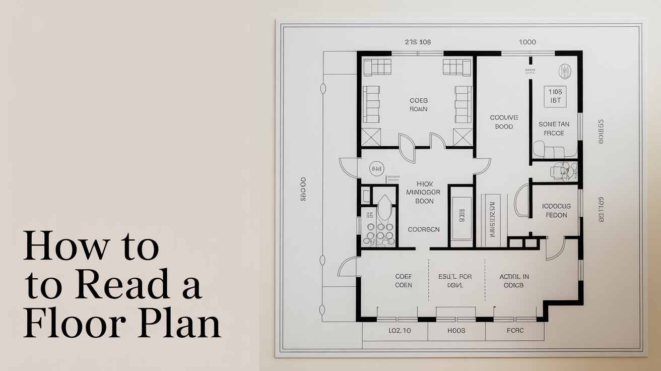
A floor plan is the bird's-eye view of a building, showing rooms, walls, doors, and windows as if the roof were lifted off and you were looking straight down. Once you know what to look for, floor plans become surprisingly easy to follow. This guide walks through each element in plain language so you can pick up any residential floor plan and understand what it's showing.
Before going further, check out What Is a Floor Plan? A Beginner's Guide if you want a broader overview of what floor plans are and where they come from. This article picks up from there and focuses on the practical skill of reading one.
Start With the Title Block and Scale
Before you try to make sense of the rooms themselves, look at the bottom-right corner of the sheet (or sometimes along one edge). This area is called the title block, and it tells you a few things you need before reading anything else:
- Sheet title, usually something like "Floor Plan," "First Floor Plan," or "Level 1"
- Scale, expressed as a ratio, such as 1/4" = 1'-0" (in the US) or 1:50 (metric). This tells you how the drawing relates to the real building
- North arrow, a small compass symbol showing which direction on the page is north
- Drawing number and revision date, useful if you ever need to confirm you have the current version
The scale matters because the actual plan is smaller than the real building. At 1/4" = 1'-0", every quarter-inch on paper represents one foot (about 30 cm) in reality. A room that measures 3 inches across on paper is 12 feet (3.65 m) wide in the building.
What If You Don't Know the Scale?
If a digital version doesn't have a clear scale, look for a graphic scale bar, a small ruler printed directly on the sheet. You can hold a ruler up to it and figure out the ratio. On a printed plan, you can use an architect's scale rule (a triangular ruler with multiple scales along its edges) to measure rooms directly.
Reading the Walls
Walls show up as thick, solid lines. The thickness of those lines in the drawing actually corresponds to the thickness of real walls:
- Exterior walls are drawn thicker because they're physically thicker, typically 6 inches (150 mm) or more when you include insulation, framing, and cladding
- Interior partition walls are thinner on the drawing, usually 4 to 5 inches (100 to 127 mm) for standard framing
- Structural walls and masonry walls may appear with a distinct hatch pattern (diagonal lines or solid fill) inside them to indicate a different material
The space between two parallel lines is the wall itself. The open space within those walls is the room. When you see a gap in a wall line, that's almost always a door or window opening.
Dashed Lines Inside Rooms
You might notice dashed or dotted lines running through rooms. These are hidden lines, indicating something above the cut plane. A beam overhead, a change in ceiling height, or an archway above door height might all show up this way. A notation near the line usually clarifies what it represents.
Doors: The Arc That Tells You the Swing
Doors are drawn as a thin straight line (the door panel itself) plus an arc that sweeps from the door's hinged edge to its open position. That arc traces the path the door travels when it swings open.
Reading the arc tells you:
- Which side the hinges are on, the arc originates from the hinge side
- Which way the door opens, into the room or out of it
- How much floor clearance you need, the swept arc should be kept clear of furniture
A pocket door (one that slides into the wall) shows as two thin parallel lines at the opening with no arc. A sliding glass door looks like two overlapping rectangles in the opening. A bi-fold door, common on closets, shows as two short panels in a V shape.
For a deeper look at how doors and windows are represented, see Door and Window Symbols on Floor Plans.
Windows: Lines Across the Wall
Windows appear as three thin parallel lines crossing the wall at the opening. The outer two lines represent the wall edges at the opening; the middle line (or two close lines) represents the glass. In some drawing styles, the lines include a thin rectangle or a slightly different treatment for the sill.
On a floor plan, you can't tell much about window height or sill height from the plan view alone. Exterior elevations (the front/side/rear view drawings) show that information. But the plan does tell you the width of each window and where it sits in the wall.
Room Labels and Dimensions
Every room on a professional floor plan is labeled. You'll see the room name ("Kitchen," "Bedroom 2," "Bath") and sometimes the room's dimensions printed inside it, like 12' x 14' (3.65 m x 4.27 m). These dimensions typically measure to the interior face of the walls (called "clear" or "net" dimensions), not to the outside of the framing.
Separate dimension strings run along the outside of the building and along interior walls. These are thin lines with tick marks or arrows at each end, showing the measured distance between two points. Dimension strings often stack in layers:
- The innermost string shows individual elements (a window width, a distance to a corner)
- The middle string shows room or bay sizes
- The outermost string shows the total building dimension
If the numbers in a string don't add up to the total, check the drawing notes. Sometimes the plan uses rough framing dimensions while the overall dimension uses finish dimensions, and they won't perfectly reconcile.
Common Floor Plan Symbols at a Glance
| Symbol | What It Represents |
|---|---|
| Thick solid lines | Walls |
| Arc at wall opening | Door swing |
| Three lines across wall | Window |
| Rectangle with "X" | Casement or skylight (context-dependent) |
| Circle with cross | Ceiling light fixture |
| Triangle pointing up | Stair going up |
| Triangle pointing down | Stair going down |
| "W/D" inside a rectangle | Washer/dryer |
| Small rectangle on wall | Switch or outlet (electrical plans) |
| Hatch pattern in wall | Masonry, concrete, or insulation (check the legend) |
Every set of plans should include a symbol legend somewhere on the sheets. When in doubt, find the legend before assuming what a symbol means, since conventions can vary between drafters and regions.
Stairs and Level Changes
Stairs on a floor plan look like a series of parallel lines representing the treads, with an arrow and the word "UP" or "DN" (down). The arrow points in the direction of travel. On the upper floor plan, the same staircase appears with "DN" and a dashed line partway through the stairs, showing where the drawing's imaginary cut plane intersects.
A ramp shows as two diagonal lines converging toward the lower end, with an arrow and a slope ratio noted alongside it, such as 1:12 (meaning the surface rises 1 unit for every 12 units of horizontal run). Slope requirements for accessibility ramps vary by building code and location.
Reading Bathrooms and Kitchens
Bathrooms and kitchens pack a lot of fixtures into small spaces, so their floor plan symbols are more detailed than other rooms.
Bathrooms
- Toilet: drawn as an oval (the bowl) attached to a narrow rectangle (the tank), positioned against a wall
- Bathtub: a rectangle, usually 5 feet (1.52 m) long, with an oval inside it representing the tub's interior
- Shower: a square or rectangular outline, often with a small diagonal line in one corner showing the drain location
- Sink/vanity: a small rectangle along the wall, sometimes with a circle inside (the bowl)
Kitchens
- Countertops: narrow rectangles along walls, typically 24 to 25 inches (61 to 64 cm) deep
- Island or peninsula: a freestanding rectangle in the room with clearance space around it
- Sink: a rectangle with one or two compartments drawn inside the counter
- Range or cooktop: a rectangle with circles representing burners
- Refrigerator: a rectangle, usually 30 to 36 inches (76 to 91 cm) wide, often with a door arc
What to Check Before Using a Floor Plan for Real Decisions
A floor plan communicates a lot, but it's one drawing in a larger set. If you're making decisions about a renovation, purchase, or build based on floor plans, keep these points in mind:
- Verify room sizes yourself. Printed dimensions may reflect design intent. Actual conditions in older or remodeled homes can differ.
- Check ceiling heights on the section or elevation drawings. The floor plan alone doesn't show them.
- Look for notes and specifications. Small text notes on the plan (and in separate specification documents) often carry critical details that don't fit in the drawing.
- Building codes and local requirements vary. Minimum room sizes, ceiling heights, egress window sizes, and hallway widths differ by jurisdiction and change over time. Always confirm requirements with your local building department.
- Have a licensed professional review real plans. If you're using plans for construction, permitting, or a purchase decision, a licensed architect or engineer should review them. This guide is educational; it's not a substitute for professional advice.
Once you're comfortable reading the rooms and symbols, How to Measure a Room and Sketch a Floor Plan shows you how to create your own basic floor plan from measurements you take yourself, which is a great way to deepen your understanding of how the drawings relate to real space.
Frequently Asked Questions
What does a dashed line on a floor plan mean?
A dashed or hidden line on a floor plan usually shows something that exists above the horizontal cut plane of the drawing. Common examples include a beam, a soffit, a header above a doorway, or a change in ceiling height. The plan should include a note or legend explaining what the dashed line represents. If no note is present, check other drawings in the set (such as reflected ceiling plans or sections) for clarification.
How do I know which direction a door swings open?
The arc drawn at the door opening shows exactly where the door travels. The arc starts at the hinge side of the door and sweeps through 90 degrees to where the door sits when fully open. If the arc sweeps into a room, the door opens inward. If it sweeps into a corridor or adjacent space, it opens outward. When furniture placement or clearance matters, trace the arc carefully and make sure that path stays clear.
Why don't the dimension numbers on a floor plan always add up?
Dimension strings can use different reference points. An inner string might measure from the center of a wall stud to the center of another stud (rough framing), while the outer overall dimension measures from exterior face to exterior face (finish dimensions). The difference accounts for half-wall thicknesses on each end. Additionally, some dimensions are rounded, which introduces small discrepancies. If the numbers are significantly off, flag it with the architect or drafter before construction.
Can I figure out ceiling height from a floor plan?
No. A standard floor plan only shows the horizontal layout at a fixed cut height (typically about 4 feet, or 1.2 m, above the floor). Ceiling heights appear on section drawings (a vertical cut through the building) or on interior elevation drawings. Some plans include a note inside each room stating the ceiling height, such as "9' CLG" meaning a 9-foot (2.74 m) ceiling, but this is a note rather than something the plan drawing itself can show geometrically.
What is the difference between a floor plan and a blueprint?
Technically, a blueprint was a specific printing process (white lines on blue paper) that was common in the twentieth century. The word is still used informally to mean any set of architectural or construction drawings. A floor plan is one specific type of drawing within a full drawing set. So a "blueprint" might include a floor plan along with site plans, elevations, sections, and other sheets, while a floor plan by itself is just the overhead room layout view.