How to Read a Section Drawing
Learn what a section drawing shows, how to find it in a plan set, and what each part means—explained plainly for beginners.
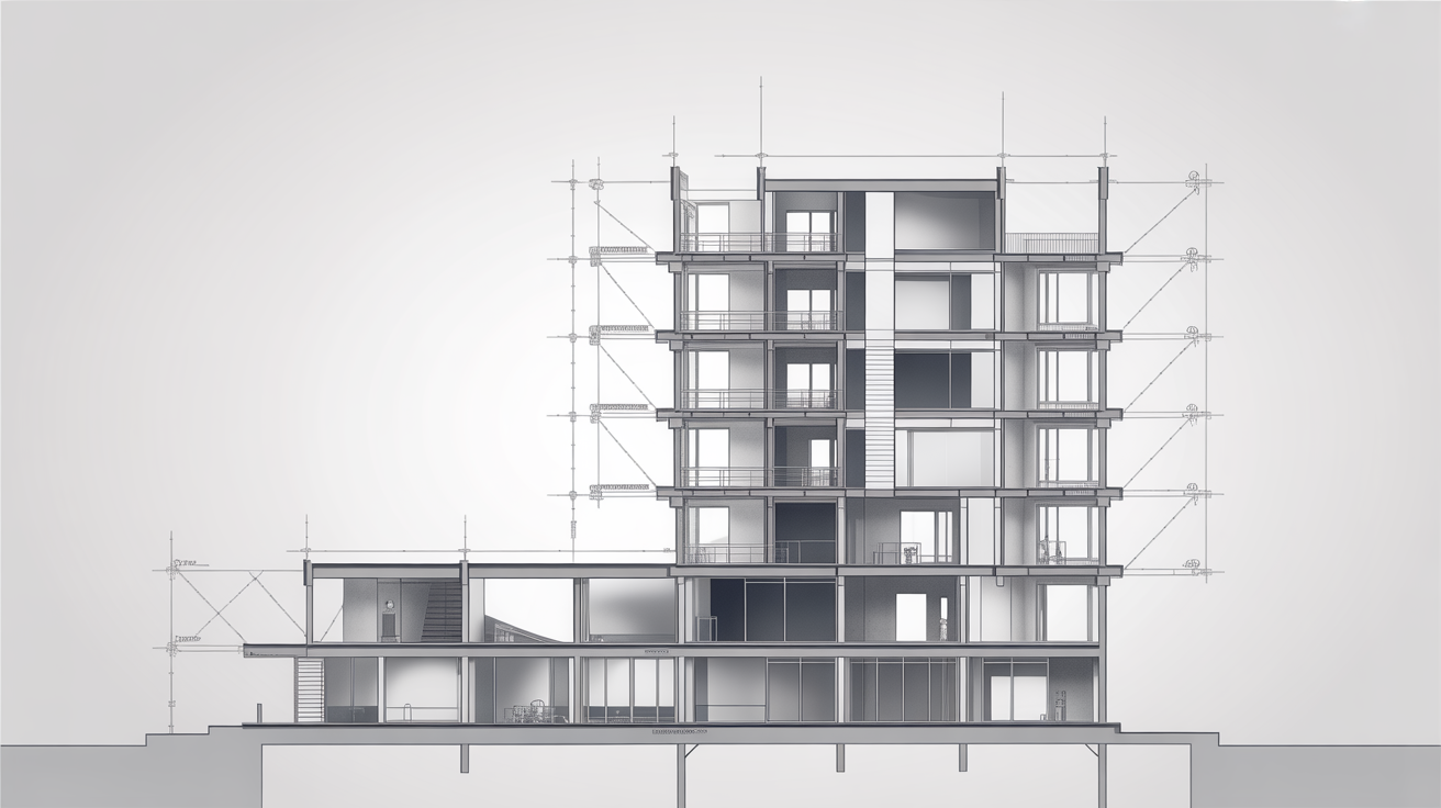
Pick up a set of house plans and flip past the floor plans. You will eventually land on a drawing that looks like someone sliced the building in half and pulled the two pieces apart so you can see inside the walls, floors, and roof. That drawing is a section, and once you know how to read one, a lot of things that look mysterious on a floor plan suddenly make sense.
This guide explains what a section drawing is, how to find the cut line that tells you where the slice was made, and what all the parts of the drawing communicate.
What a Section Drawing Actually Shows
A floor plan shows a building as if you removed the roof and looked straight down. A section drawing takes a different approach: it shows a vertical slice through the building, the way you might cut a loaf of bread to see what's inside.
The slice can run in any direction, but it is usually made at a point that shows the most useful information, such as through a staircase, a change in ceiling height, or a complex wall assembly. The resulting view lets you see:
- Floor-to-floor heights and the total building height
- Ceiling heights in each room
- Roof pitch and structure (rafters, trusses, ridge beam)
- Foundation type and how deep it goes below grade
- Wall construction (framing, insulation, sheathing layers)
- How floors are built (joists, subfloor, finishes stacked on top of each other)
- Stairs including rise, run, and headroom
- Window and door head heights as seen from the side
A floor plan cannot tell you any of these things reliably. The section is the drawing that answers "how tall is that?" and "what is that wall made of?"
How to Find the Section Marker on the Floor Plan
You do not just flip to a section drawing cold. There is a symbol on the floor plan that tells you exactly where the imaginary cut was made and which direction you are looking. That symbol is called a section callout or section marker.
What the section callout looks like
The callout is typically a circle (sometimes a hexagon or rectangle, depending on the firm's drawing standards) split in half by a line. Inside the circle you will usually see:
- A number or letter in the top half (this is the drawing number for the section itself)
- A sheet reference in the bottom half (this is the sheet number where the section drawing lives)
Extending from the circle is a dashed or dash-dot line that runs across the floor plan. This is the cut line. It shows exactly where the imaginary slice passes through the building.
Arrows on the cut line point in the direction you are looking when the slice is made. If the arrows point toward the bottom of the page, the section view looks toward the bottom of the building plan. Always check which way the arrows point before reading the section, or the drawing will appear to be mirrored.
A worked example
Suppose you see a callout on a floor plan that reads "3" over "A3.1". You would flip to sheet A3.1, find drawing number 3, and that is your section. The cut line on the floor plan tells you it ran east to west through the living room, and the arrows tell you you are looking north. The section drawing will show everything north of the cut line from ground to roof.
The Parts of a Section Drawing
Once you are looking at the section itself, you will see several consistent elements.
Ground line and below-grade conditions
Near the bottom of the drawing, a heavy line or a hatched zone marks the ground. Below it you will see the foundation, which might be a concrete slab poured at grade, a stem wall with a crawl space, or a full basement. The type of foundation affects ceiling height in rooms above and how moisture is managed, so builders pay close attention to this part.
Structural layers from bottom to top
The section shows each structural layer as a separate element with its own line weight and often its own hatch pattern. A typical wood-framed floor assembly, for instance, might show: finish flooring, plywood subfloor, floor joists (drawn as two parallel lines for the joist depth), and possibly a ceiling finish on the underside.
The same logic applies to walls. You might see: interior drywall, a stud cavity (shown as an empty rectangle or with batt-insulation hatch marks), sheathing, a weather-resistant barrier, and exterior cladding, all stacked side by side in the wall thickness.
Height dimensions
Dimension strings run vertically along the edge of a section drawing the same way horizontal dimension strings run across a floor plan. You will typically see dimensions for:
- Finished floor to finished ceiling in each room (a standard 8 ft / 2.44 m ceiling will read as 8'-0" or 2440)
- Plate height (the top of the wall framing before the roof starts)
- Ridge height or total building height above grade
- Headroom at stairs (many codes require a minimum of 6'-8" / 2.03 m; confirm with your local building department)
- Foundation depth below grade
Dimensions in US drawings typically use feet and inches written as 8'-6" (8 feet, 6 inches). Metric drawings state millimeters or meters directly. Both systems appear in published plan sets depending on the region and the architect, so always check the drawing's title block for the unit convention.
Materials shown by hatch patterns
Cut surfaces in a section are filled with hatch patterns that identify the material. Conventions vary between offices, but a legend (sometimes called a materials key or general notes sheet) should be included in the drawing set. Common patterns include:
| Material | Typical hatch pattern |
|---|---|
| Concrete | Small dots or gravel pattern |
| Concrete masonry unit (CMU) / block | Repeating rectangle grid |
| Structural steel | Solid black fill (small sections) |
| Wood (cut face) | Diagonal crossed lines |
| Insulation | Zigzag / batting pattern |
| Earth / fill | Triangle pattern or stippled dots |
| Gypsum board / drywall | Thin parallel lines |
If your drawing set does not include a legend, the section callout may reference a detail drawing that explains the assembly in a larger scale.
Notes and references to detail drawings
Circles with a line through them on a section drawing are detail callouts. They work the same way as section callouts: the top number is the detail drawing number and the bottom number is the sheet where you find it. Details zoom in on a small part of the section, often at a scale of 1:5 or 3" = 1'-0", to show how pieces of the wall, roof edge, or window frame connect.
To fully read a section, you often need to follow these references outward to the detail sheets. The section gives you the big picture; the details fill in the construction specifics.
Building Sections vs. Wall Sections
A full building section cuts all the way through the building from one exterior wall to the other, showing every floor level and the roof. A wall section (sometimes called a wall type detail) is a narrower cut focused on just one wall assembly, usually from the top of the foundation to the roof edge. Wall sections are drawn at a larger scale (1:10, or 1-1/2" = 1'-0" in imperial) to show each layer of the wall in detail.
Both types use the same reading conventions. The difference is scope and scale, not the symbols or conventions used.
How Sections Relate to the Rest of the Drawing Set
A section drawing does not stand alone. To get the full picture you need to read it alongside the floor plans (to understand the room layout), the elevation drawings (to see the exterior appearance), and any associated details.
For a broader look at all the sheet types that appear in a plan set, see What's in a Set of Construction Drawings?. If you want to understand how a building looks from the outside and how those exterior views connect to section information, Understanding Building Elevations explains elevations from scratch. For the plot of land the building sits on, How to Read a Site Plan covers grades, setbacks, and property lines.
Tips for Reading Sections as a Beginner
A few habits make sections easier to follow:
- Always locate the cut line on the floor plan first. Knowing where the slice was made and which direction you are looking prevents confusion about which rooms you are seeing.
- Read dimensions before you interpret hatch patterns. Get the heights in your head first, then study the materials.
- Keep the floor plan and section open at the same time. Cross-referencing is how the two drawings tell a complete story.
- Notice what the section does NOT show. Anything behind the cut line may not appear. If a room you expect to see is missing, check whether it falls on the other side of the cut.
- Use the detail callouts. A section tells you what is there; the details tell you how it is built. Do not skip them.
Drawing conventions, material hatch patterns, and dimension standards vary by region and by architectural office. Always confirm specific construction details with a licensed architect or engineer, and check your local building department's requirements before using any plan set for construction.
Frequently Asked Questions
What is the difference between a section drawing and an elevation drawing?
An elevation shows the exterior face of a building as seen straight on from outside, without cutting through it. A section is a cut through the building that reveals the interior structure from floor to roof. An elevation shows you what the outside looks like; a section shows you what is inside the walls, floors, and roof.
How do I know which section drawing matches which cut line on the floor plan?
The section callout on the floor plan contains two numbers: the drawing number (top) and the sheet number (bottom). Find that sheet in the plan set, then find the drawing with the matching number. The arrows on the cut line tell you which direction you are looking.
Do all buildings have section drawings?
Most residential and commercial buildings have at least one building section and one or more wall sections in their construction drawings. Simpler projects might include only a basic section; complex buildings can have many. If you are looking at permit drawings, the building department will usually require at least one section to show floor-to-ceiling heights, roof framing, and foundation depth.
Why does the section show some walls as solid black and others as just outlines?
The solid fill (or heavy hatching) shows surfaces that were cut by the section line. The outlines show surfaces that are visible in the background but were not sliced through. This distinction helps you separate what was cut from what is simply in view.
Can I figure out ceiling height from a floor plan alone?
A floor plan may include a note stating the ceiling height for a room (such as "9'-0" CLG"), but it cannot show you the structural layers that determine that height or how it relates to the floor above. A section drawing is the reliable source for confirmed heights and the structural assembly that achieves them. Always cross-reference both sheets before drawing any conclusions about clearances or room volumes.