What Is a Reflected Ceiling Plan?
A reflected ceiling plan shows what's happening above your head. Learn why it's drawn as a mirror image and how to read its lights, soffits, and heights.
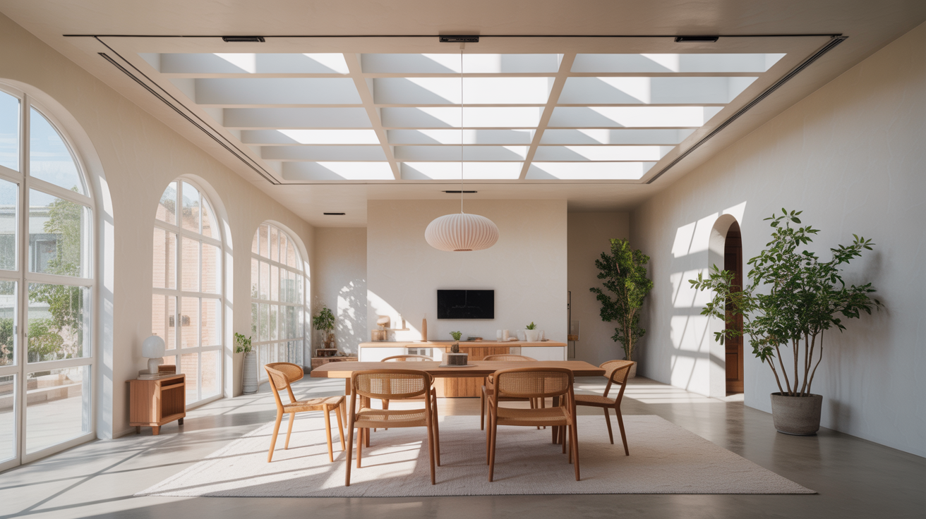
If you have worked your way through a floor plan and started flipping through the rest of a drawing set, you have probably landed on a sheet that looks almost like the floor plan you just studied, but not quite. The walls sit in roughly the same places and the room shapes match, but instead of furniture and door swings, this sheet is covered in circles, squares, and grid lines you have never seen before. That sheet is the reflected ceiling plan, usually labeled RCP in the title block, and it is one of the more confusing pages for anyone who has only ever looked down at a floor plan.
The good news is that once you understand the trick behind how it is drawn, the rest falls into place. This guide covers what an RCP is for, why it looks the way it does, and how to read the symbols so you can connect what is happening over your head to the rooms you already recognize.
What a Reflected Ceiling Plan Actually Shows
A reflected ceiling plan is a drawing of the ceiling, room by room, showing everything that lives up there: light fixtures, ceiling fans, smoke detectors, sprinkler heads, HVAC diffusers and grilles, access panels, soffits, and any changes in ceiling height. If the floor plan tells you where the walls, doors, and rooms are, the RCP tells you what is happening in the space above those rooms.
A ceiling does a lot of work. It houses the lighting layout, often hides ductwork and framing behind a dropped section, and can signal something architecturally important, like a vaulted ceiling over a living room. None of that shows up on the floor plan, because the floor plan is a horizontal slice taken at about waist height, looking down. The RCP is a separate drawing built to capture what is above that slice.
On a small residential set, the RCP might be tucked into a corner of the floor plan sheet or combined with the electrical plan. On a larger commercial set, it is almost always its own dedicated sheet. Either way, once you know to look for it, you will start noticing it in nearly every full drawing set.
Why It's Drawn Looking Up, Not Down
Here is the part that trips up most beginners: a reflected ceiling plan is drawn as if you are lying on the floor looking straight up, but the walls stay in the same positions as the floor plan. That creates a mirror-image effect that catches people off guard.
Picture a room with a window on the east wall. On the floor plan, looking down, that window sits on the right side of the room if east is to the right. A true mirror reflection would swap sides for some ceiling features relative to that wall, since your viewpoint has flipped from looking down to looking up. In practice, drafters keep the walls in the same plan position as the floor plan so the two sheets line up. What actually reflects is the direction you are facing, not the wall layout: think of it less like a mirror swapping left and right, and more like rolling onto your back, so the walls stay put but you now see the surface above you instead of below.
This convention exists because it is the only way to draw a ceiling that stays useful. Drawing it as if you were floating above the building looking down through the roof would show the tops of walls, not what a contractor installing recessed lights needs to know. Looking up from inside the room, the way you actually experience the space, shows fixture placement the way it will really appear once you stand under it.
The practical upshot: room outlines and wall positions match up directly between the two sheets. You do not need to flip the drawing around in your head. The "reflected" part refers to the viewing direction, not to a left-right swap of the layout.
Reading the Symbols on an RCP
Once you know what you are looking at, the symbols on an RCP are fairly consistent across most sets, even though exact styles vary by architect. Here are the ones you will run into most often.
Light fixtures. Recessed can lights are usually small circles, sometimes with a smaller circle or dot inside for the trim. Surface-mounted fixtures appear as slightly larger circles or squares, linear fixtures like LED strip lights show up as long rectangles, and pendant lights are often a circle with a center dot and a drop line, sometimes labeled with a mounting height.
Switches and controls. A lowercase "s" near a wall marks a switch, connected to a fixture by a dashed line called a switch leg. That line tells you which switch controls which light, useful if you are trying to figure out a room's wiring before it gets built.
Ceiling fans. A circle with a small "x" or a stylized blade shape at the center, often labeled "CF."
Life safety devices. Smoke detectors appear as a circle with "SD" beside it. Sprinkler heads, on projects that have them, are small circles with short lines, like a tiny asterisk.
HVAC elements. Supply diffusers, which push conditioned air into the room, and return grilles, which pull it back out, are rectangles or squares with a directional arrow pattern inside; round diffusers appear as circles with crossed lines.
Access panels. A small square labeled "AP" marks a hatch used to reach something hidden above the ceiling.
Ceiling grid lines. A suspended ceiling made of drop-in tiles shows up as a repeating grid, usually two feet by two feet or two feet by four feet.
Every drawing set includes a symbol legend, usually on an earlier sheet, and it is worth checking that legend against the RCP rather than assuming every architect uses identical symbols.
Connecting the RCP Back to the Floor Plan
The real skill in reading an RCP is not memorizing symbols in isolation, it is learning to hold both drawings in your head at once. A practical way to build that habit is to pick one room, find it on the floor plan, then find the same room on the RCP and walk through what you see.
Start by confirming the wall lines match between the two sheets, which tells you that you are looking at the same space. Next, look at where the fixtures land relative to the furniture layout, if the floor plan shows one. A pendant light centered over a dining table, or recessed cans arranged around a kitchen island, tells you the lighting was planned around the room's actual use rather than spaced evenly across the ceiling.
Then check for anything the RCP shows that has no equivalent on the floor plan, since that is where the useful new information lives: a soffit outline around a kitchen perimeter, a stepped line marking a ceiling height change, or a shaded area indicating a different ceiling material.
For the full context of how the RCP fits alongside the other drawings in a set, see what's in a set of construction drawings. Because ceiling heights and soffits are really a vertical story, how to read a section drawing confirms that same information from a cut through the building, seen from the side instead of from below.
Ceiling Height Changes, Soffits, and Bulkheads
One of the most useful things an RCP does is flag where the ceiling is not flat. A soffit is a lowered section of ceiling, often built to hide ductwork or structural elements, or simply to create a visual break above kitchen cabinets. A bulkhead is a similar lowered element, often running as a strip along one edge of a room. On the RCP, these show up as an outlined area with a note or dashed line marking the change, frequently with a height called out, something like "soffit at 7'-6" AFF," meaning the underside sits seven feet six inches above finished floor.
Vaulted or tray ceilings work the other direction, rising instead of dropping, usually marked with a note and a line showing where the slope or step-up begins.
A floor plan cannot show vertical information at all, so any ceiling height that is not the room's standard height has to appear on the RCP, in a note, or on a section drawing. If you spot a soffit or a height change on the RCP and want to see how tall it is relative to the surrounding walls, understanding building elevations shows those vertical dimensions from the outside in a way the RCP alone does not.
Frequently Asked Questions
Is a reflected ceiling plan required on every project?
Not always. Small residential remodels with a flat ceiling and standard lighting sometimes skip a dedicated RCP and just note fixtures on the floor plan or electrical plan. Once a project has a suspended ceiling, multiple ceiling heights, or a complex lighting design, an RCP becomes standard practice.
Why not just draw the ceiling the same way as the floor, looking down?
Looking down through the roof would show the tops of walls, not the ceiling surface as you experience it standing in the room. Looking up from inside the space lets the drawing show fixtures, soffits, and finishes the way they will really appear overhead, which is what a contractor or electrician actually needs.
How do I know which switch controls which light on an RCP?
Look for a dashed line running from a switch symbol, usually a lowercase "s" near a wall, to one or more fixture symbols. That switch leg shows the wiring relationship between the control and the fixture it operates, and a room with several switches typically has a separate line for each one.
Do the room shapes on the RCP ever not match the floor plan?
They should match closely, since both drawings represent the same walls. A real mismatch, like a wall shown in a different spot or missing entirely, is worth flagging to whoever produced the set, since it usually means the drawings have not been fully coordinated yet.